Here i am going to post tutorial to flash ESC with SimonK firmware. This firmware specially designed for multirotor application. I would like to thank SimonK(for firmware), Timecop(for some imp instructions), LazyZero(for great flash tool), TomSnow(for ESC database), Ashta Sir(for posting topic over RCI). In this tutorial i will show you how to flash HK F-20A ESCs using LazyZero flash tool. The process is same for F-30A ESCs as well.
Note: Firmware flashing involves risk of damaging ESC permanently, do it at your own risk.
FEATURES OF FLASHED ESC
WHY NEED TO FLASH FIRMWARE?
Before you go any further please check this nice wiki over OpenPilot website
http://wiki.openpilot.org/display/Doc/RapidESCs
Here is detailed information about firmware flashing
https://github.com/sim-/tgy
Also please check original topic over RCG
http://www.rcgroups.com/forums/showthread.php?t=1513678
Here is one more tutorial over RCI by Astha Sir
http://www.rcindia.org/servos-gyros-and-all-electronics/esc-do-it-yourseld-firmware-flashing/
REQUIREMENT:
1. USBASP CABLE
http://www.hobbyking.com/hobbyking/store/__21321__USBasp_AVR_Programming_Device_for_ATMEL_proccessors.html
2. Servo extension leads(to connect usbasp to the pin)
http://www.hobbyking.com/hobbyking/store/uh_viewitem.asp?idproduct=10412&aff=61689
3. 1-1.5mm thick plastic chips(to make pin)
4. Metal leads(to connect with the pads)
5. Hot glue
6. LazyZero flash tool(get latest stable release)
http://lazyzero.de/en/modellbau/kkmulticopterflashtool
7. Turnigy USB linker(optional, to upgrade firmware of allready flashed ESCs)
http://www.hobbyking.com/hobbyking/store/__10628__Turnigy_USB_Linker_for_AquaStar_Super_Brain_.html
PROCEDURE:
If you are yet to buy new ESCs for your multirotor and want to flash them then it would be better to buy those ESCs that can be flashed easily without much efforts. Some of them are HK F-20A and F-30A ESCs. They have been tested and flashed by many users and best part is you don't need to remove whole shrink tube.
1. Whatever ESC you have first make sure which firmware is compatible with the ESC. Check the ESC database(spreadsheet) below.
https://docs.google.com/spreadsheet/lv?key=0AhR02IDNb7_MdEhfVjk3MkRHVzhKdjU1YzdBQkZZRlE
You will find all information in the spreadsheet to flash your ESC.

In our case we are flashing HK F-20A ESCs as shown in the pic below.

Search and check the same in the database. You will see that position of programming pads is in row, at the backside just near motor output.


One more imp thing you must know is type of firmware file. In our case it's "bs_nfet.hex"
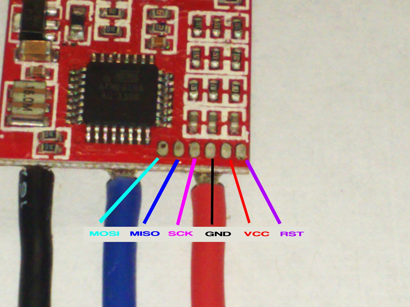
Always double, triple check which firmware you require to flash an ESC. Flashing wrong firmware to the ESC might lead you to the dead/fried ESC on power up. Also check the pinout order. There are 6 pinout in this ESC.
MOSI, MISO, SCK, GND, VCC, RST
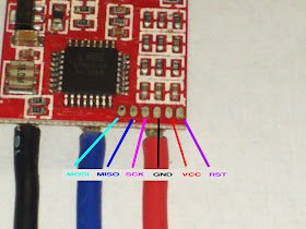
Order of this pinout may be different for other ESCs.
2. Once you confirm position of pads, pinout order and type of firmware, you can now go ahead. You just need to cut the portion of heat shrink tube above the programming pads so you can connect your DIY pin easily.

3. Now you have to make pin so you can connect your USBASP programmer to the ESC. Since all ESCs have different pinout order and positions, there's no readymade pin available in the market so you will have to make this yourself at home. You can directly solder wires on the ESCs but if you have more than one ESC to flash then it's pain and complex work as the gape between these pads is really less.
Now to make diy pin you need
20mm x 10mm x 1-2mm
plastic chips or any material like thin balsa sheet. Now measure the distance between ESC programming pads and make 6 slots on both chips at the same distance.

Now you need 6 metal leads to put them in the slots.

I got them from register as shown in the pic above, you can use any sort of that. Now put them in each slot and sandwich them between two chips and apply hot glue near the joint to make it firm and let it dry for some time.

Now get servo extension wire and cut the female pins and solder those ends to the pin that we just made. Check below pic

From the other end of servo extension wire remove those servo leads gently out of the plastic case.

Your DIY pin setup is ready now.

4. Now check your USBASP programmer. Pinout names are allready printed on it which makes our job easy.


Take your diy pin setup and connect servo leads one by one to the programmer in correct order.

Once completed double check the whole setup and make sure pinout order from programmer to diy pin is correct. In our case it is
MOSI, MISO, SCK, GND, VCC, RST
5. You are now allmost ready to flash your ESCs. Connect programmer to the PC(green LED on). Now open LazyZero flashtool. Now select "atmega 8-based brushless ESC + enable Bootloader(8kB flash)" from the controller menu. Now select appropiate firmware from the menu. In our case it's BS-NFET. Keep the rest settings as default. The only difference between
atmega 8-based brushless ESC &
atmega 8-based brushless ESC + enable Bootloader(8kB flash) is if you select "enable bootloader" then you can later reflash your ESC with upgraded firmware using TURNIGY USB Linker using servo pin.

6. Now connect pin to the ESC. Make sure all metal leads touched and connected properly to the programming pads. You should have steady hands for that. Once confirmed hit the green button and flashing will start. It would take 2-5 seconds to complete process. During the process when programmer writing data in the ATMEGA chip you will see both green and red LEDs are on. In case connection between metal leads and pads is not firm or your hand is shaking and you lost connection you will get an error something like this.
Flash the firmware from repository.
E:\zzzzzzzzzzz\lib\avrdude\windows\avrdude.exe -C E:\zzzzzzzzzzz\lib\avrdude\windows\avrdude.conf -p m8 -P usb -c usbasp -B 8 -e -U lfuse:r:E:\zzzzzzzzzzz\tmp\/lfuse.hex:r -U hfuse:r:E:\zzzzzzzzzzz\tmp\/hfuse.hex:r
avrdude.exe: set SCK frequency to 93750 Hz
avrdude.exe: warning: cannot set sck period. please check for usbasp firmware update.
avrdude.exe: error: programm enable: target doesn't answer. 1
avrdude.exe: initialization failed, rc=-1
Double check connections and try again, or use -F to override
this check.
avrdude.exe done. Thank you.
Error during reading of high fuse.
Flashing of firmware aborted.
Don't worry your ESC isn't dead yet, connect the pin again to the ESC and keep hands steady during the whole process and it should work but if you still get an error and you are sure that pin is connected properly then scratch the pads GENTLY using cutting knife.

It happened with me once. After flashing 2 ESCs successfully rest 2 ESCs refused to take flashing. I tried several times but it was showing me an error. I had to scratch the pads bit and it went smoothly. After successful flash you will get following msg in the flash tool.
Flashing firmware from file.: E:\zzzzzzzzzzz\tmp\bs_nfet.hex
E:\zzzzzzzzzzz\lib\avrdude\windows\avrdude.exe -C E:\zzzzzzzzzzz\lib\avrdude\windows\avrdude.conf -p m8 -P usb -c usbasp -B 8 -e -U flash:w:E:\zzzzzzzzzzz\tmp\bs_nfet.hex:i
avrdude.exe: set SCK frequency to 93750 Hz
avrdude.exe: warning: cannot set sck period. please check for usbasp firmware update.
avrdude.exe: AVR device initialized and ready to accept instructions
Reading | ################################################## | 100% 0.02s
avrdude.exe: Device signature = 0x1e9307
avrdude.exe: erasing chip
avrdude.exe: set SCK frequency to 93750 Hz
avrdude.exe: warning: cannot set sck period. please check for usbasp firmware update.
avrdude.exe: reading input file "E:\zzzzzzzzzzz\tmp\bs_nfet.hex"
avrdude.exe: writing flash (8192 bytes):
Writing | ################################################## | 100% 2.17s
avrdude.exe: 8192 bytes of flash written
avrdude.exe: verifying flash memory against E:\zzzzzzzzzzz\tmp\bs_nfet.hex:
avrdude.exe: load data flash data from input file E:\zzzzzzzzzzz\tmp\bs_nfet.hex:
avrdude.exe: input file E:\zzzzzzzzzzz\tmp\bs_nfet.hex contains 8192 bytes
avrdude.exe: reading on-chip flash data:
Reading | ################################################## | 100% 1.97s
avrdude.exe: verifying ...
avrdude.exe: 8192 bytes of flash verified
avrdude.exe done. Thank you.
Congratulations! You have now your ESCs flashed with SimonK firmware. We call them Rapid ESCs. Once done connect ESC to the motor(NO PROPS) and receiver then power up the ESC for testing. If motor refuses to spin follow throttle calibration process. Do it individually with each flashed ESC
THROTTLE CALIBRATION
1. Put throttle stick to the max(bring the throttle trim to the middle if not) and power on the TX.
2. Connect an ESC to the motor and receiver(throttle channel) and power up the ESC.
3. You will get beep once(no more cyclic stock firmware beeps).
4. Bring the throttle stick down(minimum position).
5. You will get confirmation beep now.
6. It's done. Test again and motor should spin now.
If any correction found in the topic please mail me.
Note: Firmware flashing involves risk of damaging ESC permanently, do it at your own risk.
FEATURES OF FLASHED ESC
- 16MHz operation on most boards
- 16-bit output PWM with full clock rate resolution (~18kHz PWM with a POWER_RANGE of 800 steps)
- 24-bit timing and PWM pulse tracking at full clock rate resolution
- ICP-based pulse time recording (on supported hardware) for zero throttle jitter
- Immediate PWM input to PWM output for best possible multicopter response (eg: ideal for tricopters, quadcopters, etc., but NOT where where slow-start or really any significant current limiting is needed!)
- Accepts any PWM update rate (minimum ~5microseconds PWM low time)
- Optimized interrupt code (very low minimum PWM and reduced full throttle bump)
- Configurable board pin assignments by include file
- Smooth starting in most cases
- Forward and reverse commutation supported, including RC-car style reverse-neutral-forward PWM ranges, with optional braking
WHY NEED TO FLASH FIRMWARE?
Before you go any further please check this nice wiki over OpenPilot website
http://wiki.openpilot.org/display/Doc/RapidESCs
Here is detailed information about firmware flashing
https://github.com/sim-/tgy
Also please check original topic over RCG
http://www.rcgroups.com/forums/showthread.php?t=1513678
Here is one more tutorial over RCI by Astha Sir
http://www.rcindia.org/servos-gyros-and-all-electronics/esc-do-it-yourseld-firmware-flashing/
REQUIREMENT:
1. USBASP CABLE
http://www.hobbyking.com/hobbyking/store/__21321__USBasp_AVR_Programming_Device_for_ATMEL_proccessors.html
2. Servo extension leads(to connect usbasp to the pin)
http://www.hobbyking.com/hobbyking/store/uh_viewitem.asp?idproduct=10412&aff=61689
3. 1-1.5mm thick plastic chips(to make pin)
4. Metal leads(to connect with the pads)
5. Hot glue
6. LazyZero flash tool(get latest stable release)
http://lazyzero.de/en/modellbau/kkmulticopterflashtool
7. Turnigy USB linker(optional, to upgrade firmware of allready flashed ESCs)
http://www.hobbyking.com/hobbyking/store/__10628__Turnigy_USB_Linker_for_AquaStar_Super_Brain_.html
PROCEDURE:
If you are yet to buy new ESCs for your multirotor and want to flash them then it would be better to buy those ESCs that can be flashed easily without much efforts. Some of them are HK F-20A and F-30A ESCs. They have been tested and flashed by many users and best part is you don't need to remove whole shrink tube.
1. Whatever ESC you have first make sure which firmware is compatible with the ESC. Check the ESC database(spreadsheet) below.
https://docs.google.com/spreadsheet/lv?key=0AhR02IDNb7_MdEhfVjk3MkRHVzhKdjU1YzdBQkZZRlE
You will find all information in the spreadsheet to flash your ESC.
In our case we are flashing HK F-20A ESCs as shown in the pic below.

Search and check the same in the database. You will see that position of programming pads is in row, at the backside just near motor output.


One more imp thing you must know is type of firmware file. In our case it's "bs_nfet.hex"
Always double, triple check which firmware you require to flash an ESC. Flashing wrong firmware to the ESC might lead you to the dead/fried ESC on power up. Also check the pinout order. There are 6 pinout in this ESC.
MOSI, MISO, SCK, GND, VCC, RST
Order of this pinout may be different for other ESCs.
2. Once you confirm position of pads, pinout order and type of firmware, you can now go ahead. You just need to cut the portion of heat shrink tube above the programming pads so you can connect your DIY pin easily.

3. Now you have to make pin so you can connect your USBASP programmer to the ESC. Since all ESCs have different pinout order and positions, there's no readymade pin available in the market so you will have to make this yourself at home. You can directly solder wires on the ESCs but if you have more than one ESC to flash then it's pain and complex work as the gape between these pads is really less.
Now to make diy pin you need
20mm x 10mm x 1-2mm
plastic chips or any material like thin balsa sheet. Now measure the distance between ESC programming pads and make 6 slots on both chips at the same distance.

Now you need 6 metal leads to put them in the slots.

I got them from register as shown in the pic above, you can use any sort of that. Now put them in each slot and sandwich them between two chips and apply hot glue near the joint to make it firm and let it dry for some time.

Now get servo extension wire and cut the female pins and solder those ends to the pin that we just made. Check below pic

From the other end of servo extension wire remove those servo leads gently out of the plastic case.

Your DIY pin setup is ready now.

4. Now check your USBASP programmer. Pinout names are allready printed on it which makes our job easy.


Take your diy pin setup and connect servo leads one by one to the programmer in correct order.

Once completed double check the whole setup and make sure pinout order from programmer to diy pin is correct. In our case it is
MOSI, MISO, SCK, GND, VCC, RST
5. You are now allmost ready to flash your ESCs. Connect programmer to the PC(green LED on). Now open LazyZero flashtool. Now select "atmega 8-based brushless ESC + enable Bootloader(8kB flash)" from the controller menu. Now select appropiate firmware from the menu. In our case it's BS-NFET. Keep the rest settings as default. The only difference between
atmega 8-based brushless ESC &
atmega 8-based brushless ESC + enable Bootloader(8kB flash) is if you select "enable bootloader" then you can later reflash your ESC with upgraded firmware using TURNIGY USB Linker using servo pin.

6. Now connect pin to the ESC. Make sure all metal leads touched and connected properly to the programming pads. You should have steady hands for that. Once confirmed hit the green button and flashing will start. It would take 2-5 seconds to complete process. During the process when programmer writing data in the ATMEGA chip you will see both green and red LEDs are on. In case connection between metal leads and pads is not firm or your hand is shaking and you lost connection you will get an error something like this.
Flash the firmware from repository.
E:\zzzzzzzzzzz\lib\avrdude\windows\avrdude.exe -C E:\zzzzzzzzzzz\lib\avrdude\windows\avrdude.conf -p m8 -P usb -c usbasp -B 8 -e -U lfuse:r:E:\zzzzzzzzzzz\tmp\/lfuse.hex:r -U hfuse:r:E:\zzzzzzzzzzz\tmp\/hfuse.hex:r
avrdude.exe: set SCK frequency to 93750 Hz
avrdude.exe: warning: cannot set sck period. please check for usbasp firmware update.
avrdude.exe: error: programm enable: target doesn't answer. 1
avrdude.exe: initialization failed, rc=-1
Double check connections and try again, or use -F to override
this check.
avrdude.exe done. Thank you.
Error during reading of high fuse.
Flashing of firmware aborted.
Don't worry your ESC isn't dead yet, connect the pin again to the ESC and keep hands steady during the whole process and it should work but if you still get an error and you are sure that pin is connected properly then scratch the pads GENTLY using cutting knife.

It happened with me once. After flashing 2 ESCs successfully rest 2 ESCs refused to take flashing. I tried several times but it was showing me an error. I had to scratch the pads bit and it went smoothly. After successful flash you will get following msg in the flash tool.
Flashing firmware from file.: E:\zzzzzzzzzzz\tmp\bs_nfet.hex
E:\zzzzzzzzzzz\lib\avrdude\windows\avrdude.exe -C E:\zzzzzzzzzzz\lib\avrdude\windows\avrdude.conf -p m8 -P usb -c usbasp -B 8 -e -U flash:w:E:\zzzzzzzzzzz\tmp\bs_nfet.hex:i
avrdude.exe: set SCK frequency to 93750 Hz
avrdude.exe: warning: cannot set sck period. please check for usbasp firmware update.
avrdude.exe: AVR device initialized and ready to accept instructions
Reading | ################################################## | 100% 0.02s
avrdude.exe: Device signature = 0x1e9307
avrdude.exe: erasing chip
avrdude.exe: set SCK frequency to 93750 Hz
avrdude.exe: warning: cannot set sck period. please check for usbasp firmware update.
avrdude.exe: reading input file "E:\zzzzzzzzzzz\tmp\bs_nfet.hex"
avrdude.exe: writing flash (8192 bytes):
Writing | ################################################## | 100% 2.17s
avrdude.exe: 8192 bytes of flash written
avrdude.exe: verifying flash memory against E:\zzzzzzzzzzz\tmp\bs_nfet.hex:
avrdude.exe: load data flash data from input file E:\zzzzzzzzzzz\tmp\bs_nfet.hex:
avrdude.exe: input file E:\zzzzzzzzzzz\tmp\bs_nfet.hex contains 8192 bytes
avrdude.exe: reading on-chip flash data:
Reading | ################################################## | 100% 1.97s
avrdude.exe: verifying ...
avrdude.exe: 8192 bytes of flash verified
avrdude.exe done. Thank you.
Congratulations! You have now your ESCs flashed with SimonK firmware. We call them Rapid ESCs. Once done connect ESC to the motor(NO PROPS) and receiver then power up the ESC for testing. If motor refuses to spin follow throttle calibration process. Do it individually with each flashed ESC
THROTTLE CALIBRATION
1. Put throttle stick to the max(bring the throttle trim to the middle if not) and power on the TX.
2. Connect an ESC to the motor and receiver(throttle channel) and power up the ESC.
3. You will get beep once(no more cyclic stock firmware beeps).
4. Bring the throttle stick down(minimum position).
5. You will get confirmation beep now.
6. It's done. Test again and motor should spin now.
If any correction found in the topic please mail me.